Guide to Names and Functions of Components

- Do not obstruct the machine's vents. Doing so can result in fire as the internal components are overheated.
Front and Left View
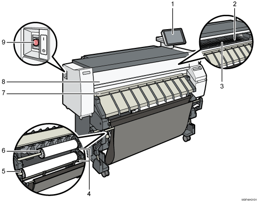
Control panel
Platen
Paper is sucked down and prevented from floating. Clean this area if the back of the printouts becomes dirty.
Paper bypass location
Load paper here when you print from the paper bypass location. Load paper print side up.
Rewind button
Press this button to load the paper roll or to remove misfed paper.
Paper Input Location 2
Load a paper roll here.
Paper Input Location 1
Load a paper roll here.
Paper output location
The printouts are delivered here.
Front cover
This is the cover of the paper bypass location. Open this cover to print from the paper bypass location, to remove misfed paper, or to clean the platen.
Main power switch
To operate the machine, the main power switch must be on. If it is off, turn the switch on.
Front and Right View
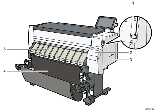
Paper holding lever
This lever holds paper that is inserted into the paper input location or the paper bypass location. Use this lever to print from the bypass location, or to remove misfed paper.
Cartridge cover
Open to replace print cartridges.
Ink collector unit cover
Open this cover to replace the ink collector unit. Ink used for maintenance collects in the ink collector unit.
Output basket
The delivered paper is stacked here.
Paper input location cover
Open to load the paper roll onto the paper input location or to remove misfed paper.
Rear View
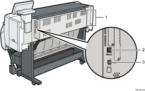
Vents
Prevent overheating. After large-volume printing, the ventilation fan may continue to work to lower the temperature inside the machine.
Ethernet interface
Used the port to connect the machine to the network or to use the remote management service (@Remote) over the Internet.
USB2.0 Interface Type B
Use the port to connect the machine and the computer with the USB cable.

 (mainly Europe)
When touching the machine, you may experience a static shock which is harmless to humans. For details, refer to the following:
https://www.ricoh-europe.com/support/health-safety/ricoh-static-shock.html