Guide to Names and Functions of Components
![]()
- Do not obstruct the machine's vents. Doing so can result in fire as the internal components are overheated.
- When moving the machine, do not hold the control panel. Doing so may damage the control panel and can result in injury or malfunction.
Front and Left View
IM C530FB
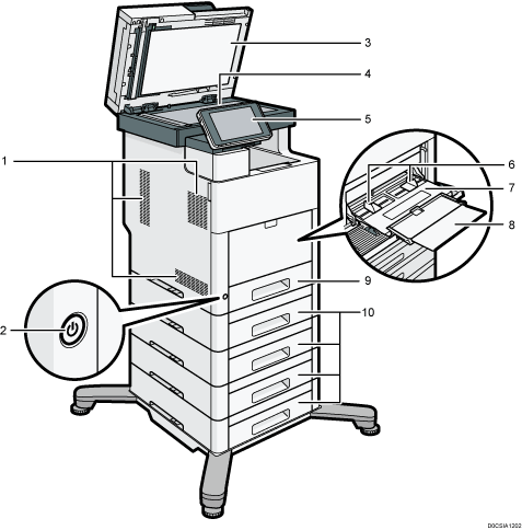
Vents
Prevent overheating.
Main power switch
To operate the machine, the main power switch must be on. If it is off, turn the switch on.
Auto Document Feeder (ADF)
Lower the ADF over originals placed on the exposure glass.
If you load a stack of originals in the ADF, the ADF will automatically feed the originals one by one.
Exposure glass
Place originals face down here.
Control panel
Paper guides
When loading paper in the bypass tray, align the paper guides flush against the paper.
Bypass tray
Use to copy or print on label paper (adhesive labels).
Extender
Pull this extender out when loading A4
 , 81/2 × 11
 or larger size paper in the bypass tray.
Paper tray
Load paper here.
Paper feed unit
Load paper here.
IM C530F
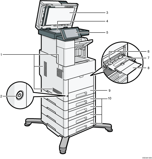
Vents
Prevent overheating.
Main power switch
To operate the machine, the main power switch must be on. If it is off, turn the switch on.
Auto Document Feeder (ADF)
Lower the ADF over originals placed on the exposure glass.
If you load a stack of originals in the ADF, the ADF will automatically feed the originals one by one.
Exposure glass
Place originals face down here.
Control panel
Paper guides
When loading paper in the bypass tray, align the paper guides flush against the paper.
Bypass tray
Use to copy or print on label paper (adhesive labels).
Extender
Pull this extender out when loading A4
 , 81/2 × 11
 or larger size paper in the bypass tray.
Paper tray
Load paper here.
Paper feed unit
Load paper here.
Front and Right View
IM C530FB
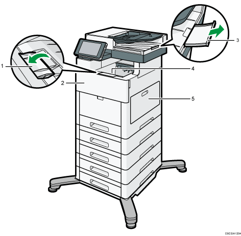
Standard tray guide
Open out the end fence to support large paper.
Front cover
Open to replace the print cartridge.
ADF's extender
Pull this extender out to support large paper.
Standard tray
Copied/printed paper and fax messages are delivered here
Right cover
Open to replace the waste toner bottle.
IM C530F
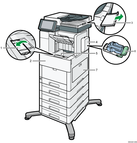
Standard tray guide
Open out the end fence to support large paper.
Front cover
Open to replace the print cartridge.
ADF's extenders
Pull this extender out to support large paper.
Finisher staple cover
Open to replace the staple cartridge.
Standard tray
Copied/printed/sorted/stapled paper and fax messages are delivered here.
Staple cartridge
Staple cartridge for the finisher. Replace the cartridge when the staples run out.
Right cover
Open to replace the waste toner bottle.
Rear and Left View
IM C530FB
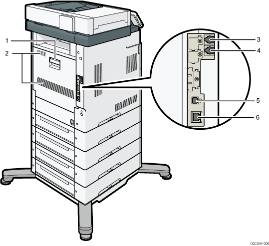
Rear cover
Open this cover when a paper jam occurs.
Vents
Prevent overheating.
LINE: G3 interface unit connector
Connect the line for fax use.
TEL: External telephone connector
Connect an external telephone set.
USB2.0 Interface Type B
Use this port to connect the machine and the computer with the USB cable.
Ethernet port
Use a network interface cable to connect the machine to a network.
IM C530F
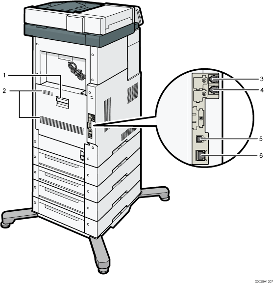
Rear cover
Open this cover when a paper jam occurs.
Vents
Prevent overheating.
LINE: G3 interface unit connector
Connect the line for fax use.
TEL: External telephone connector
Connect an external telephone set.
USB2.0 Interface Type B
Use this port to connect the machine and the computer with the USB cable.
Ethernet port
Use a network interface cable to connect the machine to a network.
