When Vertical Uneven Density Parts Appear on Printed Images
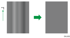
If vertical uneven density parts appear on printed images when you make a copy or print halftone images, the following function may improve the output.
If you perform the correction again, the output may improve even more.

*1 Print direction (Output direction)
![]()
This function can correct the density of halftone images evenly.
This function cannot correct the following printed images:
Halftone images in which lines or bands appear, caused by uneven density in a direction other than the direction shown in the illustration above.
Black lines or bands appear where there is no image.
Images in which characters are missing or colored white.
This function prints a test pattern. If you scan it using the scanner, you can correct uneven density automatically. When you print the test pattern, use plain paper. If you use colored paper or the backside of previously used paper, the correction may not function as intended.
You can use A4 or 8 1/2 × 11 size plain paper. Make sure the correct size of paper is loaded in the paper tray. You cannot load this paper in the bypass-tray.
![]() Press [Home] (
Press [Home] ( ) at the bottom of the screen in the center.
![]() Flick the screen to the left, and then press the [User Tools] icon (
Flick the screen to the left, and then press the [User Tools] icon (![]() ).
).
![]() Press [Machine Features].
Press [Machine Features].
![]() Press [Maintenance].
Press [Maintenance].
![]() Press [Vertical Uneven Density Correction].
Press [Vertical Uneven Density Correction].
![]() Press [Start].
Press [Start].
![]() Select paper size either [A4
Select paper size either [A4![]() ] or [81/2 × 11
] or [81/2 × 11![]() ].
].
![]() Press [Start Printing].
Press [Start Printing].
The test pattern is printed.

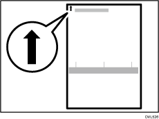
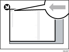
![]() Place the test pattern on the exposure glass in the following way.
Place the test pattern on the exposure glass in the following way.
Place the test pattern face down and align the arrow of the test pattern with the rear left corner of the exposure glass.

![]() Press [Start Scanning].
Press [Start Scanning].
![]() Remove the test pattern from the exposure glass.
Remove the test pattern from the exposure glass.
![]() Press [Exit].
Press [Exit].
![]() Press [User Tools] (
Press [User Tools] ( ) on the top right of the screen.
![]() Press [Home] (
Press [Home] ( ) at the bottom of the screen in the center.
![]() Check the correction result.
Check the correction result.
Print or make a copy of a halftone image, and confirm that the uneven density is properly corrected and the print results are improved. If you still care for uneven density, repeat the Steps 1 to 14.
![]()
If a scanning error message appears, the test pattern may not be set correctly. Do the following. If the error message is still displayed even after you do the following, contact your sales or service representative.
Check the orientation and position of the test pattern you set, and set it correctly.
Check if the test pattern has slipped out of the correct position, and set it correctly.
To prevent the test pattern from slipping out of the correct position when you close the ADF, place a few sheets of the same size of white paper as the test pattern behind the test pattern, and then scan it.
Vertical uneven density correction cannot be executed while the message, "The printing speed is now being limited because the internal cooling fan is active." is displayed. Perform vertical uneven density correction after the message disappears.
If there are more white or black lines in the printed image after the correction compared to before the correction, the situation may improve if you do the following. If the problem still persists, reset the correction value. For details, see Returning to the Previous Setting.
Clean the scanner, and perform the correction again. For details about cleaning, see "Maintaining Your Machine", Maintenance.
Clean the LED head, and perform the correction again. For details about cleaning, see "Maintaining Your Machine", Maintenance.
If the test pattern is creased, the machine may not perform the correction correctly. Print the test pattern again using a new sheet of paper, and then perform the correction again by scanning the new test pattern.
When you set the test pattern on the exposure glass, set it so that it is aligned with the edge of the exposure glass and not skewed.
Related topics
